Polygon Shape Filling

This entry describes a little spinoff (spun-in?) project that happened during game development.

For all kinds of reasons, I needed a utility bitmap class. Just a place to load and save bitmaps and move them around. For example, on their way to become texture maps or font.

Easy enough, for my purposes 8 bits each of RGBA is fine.

class OmImageRgba8 : OmObjectBase
{
public:
    int width = 0;
    int height = 0;
    uint32_t *pixels = 0; // malloc'd, disposed with instance
    OmImageRgba8(int width, int height);
   ~OmImageRgba8();
    void setPixel(int x, int y, uint32_t pixel);
    uint32_t getPixel(int x, int y);

    bool writeFile(std::string filePath);
    static OmImageRgba8 *readFile(std::string filePath);
}

So about ReadFile and WriteFile. I do love writing everything myself… up to a point. I’m often put off my the complexity of using Other People’s Code, when it becomes mired in a tangle of still more Library Dependencies. Makes it hard to build my project.

Happily, I found “plain old code” libraries for PNG and JPG. By “plain old code” I mean, it’s a small number of source code files that just work on a normal compiler.

LODEPNG by Lode Vandevenne for reading and writing PNG files.

JPEG-COMPRESSOR by Rich Geldreich, for reading and writing JPG files. 

These were both very easy to integrate. The ::readFile() and ::writeFile() methods on OmImageRgba8 simply look at the file extension to choose which, and only work if it’s .jpg or .png.

More features crept in over time. Some images arrive Y-up, others Y-down, so ::flipY() was added.

For debugging, it’s handy to imprint text information onto a bitmap, so ::drawF(uint32_t color, const char *fmt, …) was added. It uses a simple 8×8 pixel font. I came across this handy font some years ago, and must share its origin. The link is http://overcode.yak.net/12. It was a small image which I decomposed into static C data.

char font8x8[] = 
{
…
0x08,0x49,0x2a,0x1c,0x2a,0x49,0x08,0x00,   // 0x2a '*'
//   . . . . @ . . . 
//   . @ . . @ . . @ 
//   . . @ . @ . @ . 
//   . . . @ @ @ . . 
//   . . @ . @ . @ . 
//   . @ . . @ . . @ 
//   . . . . @ . . . 
//   . . . . . . . . 
0x08,0x08,0x08,0x7f,0x08,0x08,0x08,0x00,   // 0x2b '+'
//   . . . . @ . . . 
//   . . . . @ . . . 
//   . . . . @ . . . 
//   . @ @ @ @ @ @ @ 
//   . . . . @ . . . 
//   . . . . @ . . . 
//   . . . . @ . . . 
//   . . . . . . . . 
…
};

The font was designed by John Hall, and on the website above, he also documents some other code and tech work, and some aeronautical items, and his descent and demise due to skin cancer. So I always think a few kind words of thanks to this unknown and lost fellow coder and this one part of his legacy that I use. Thanks John.

And somewhere along the way I wanted to do some generative art, so added a basic antialiased Rectangle Fill method. Handles the edges and corners special for partial coverage, and fills the broad interior. Fun enough.
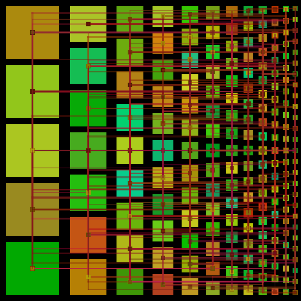
(generative art)

But that slippery slope let up to September 2022 when I thought, All the cool kids have implemented a scanline polygon fill, it’s time for me.

Filling polygons is kind-of a big bother, keeping track of edge lists and numbers and stuff. Oh well! Computers and programmers love that kind of thing. Here’s the basic approach.

I’ll define polygon as one or more closed loops of straight edges. The polygon is defined by the vertices, and each vertex is shared by two edges.

For a simple polygon fill, we fill each pixel if and only if the center of the pixel is within the polygon. 
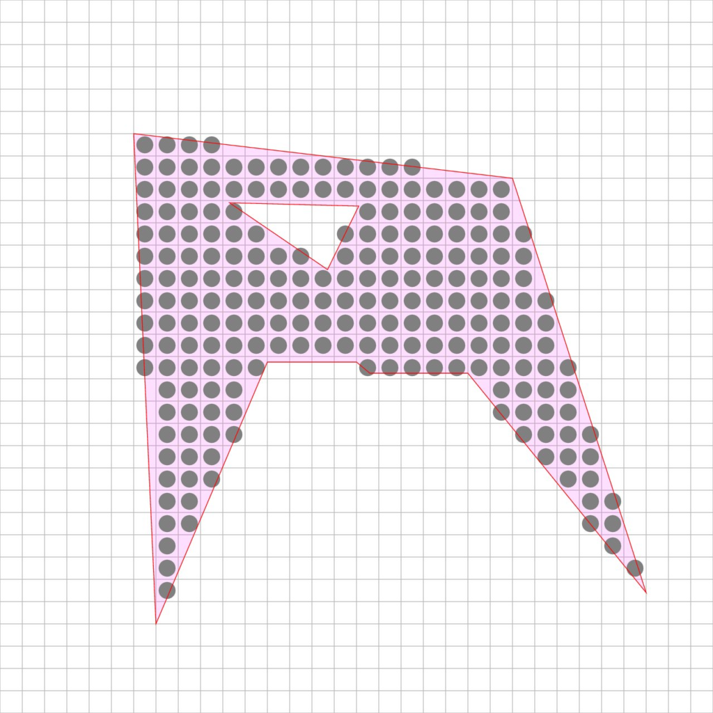
(A polygon with two paths)

(We’ll discuss partial coverage later, I promise.)

Essentially, we want to ask each and every pixel, “Is the center of this pixel within the polygon.”
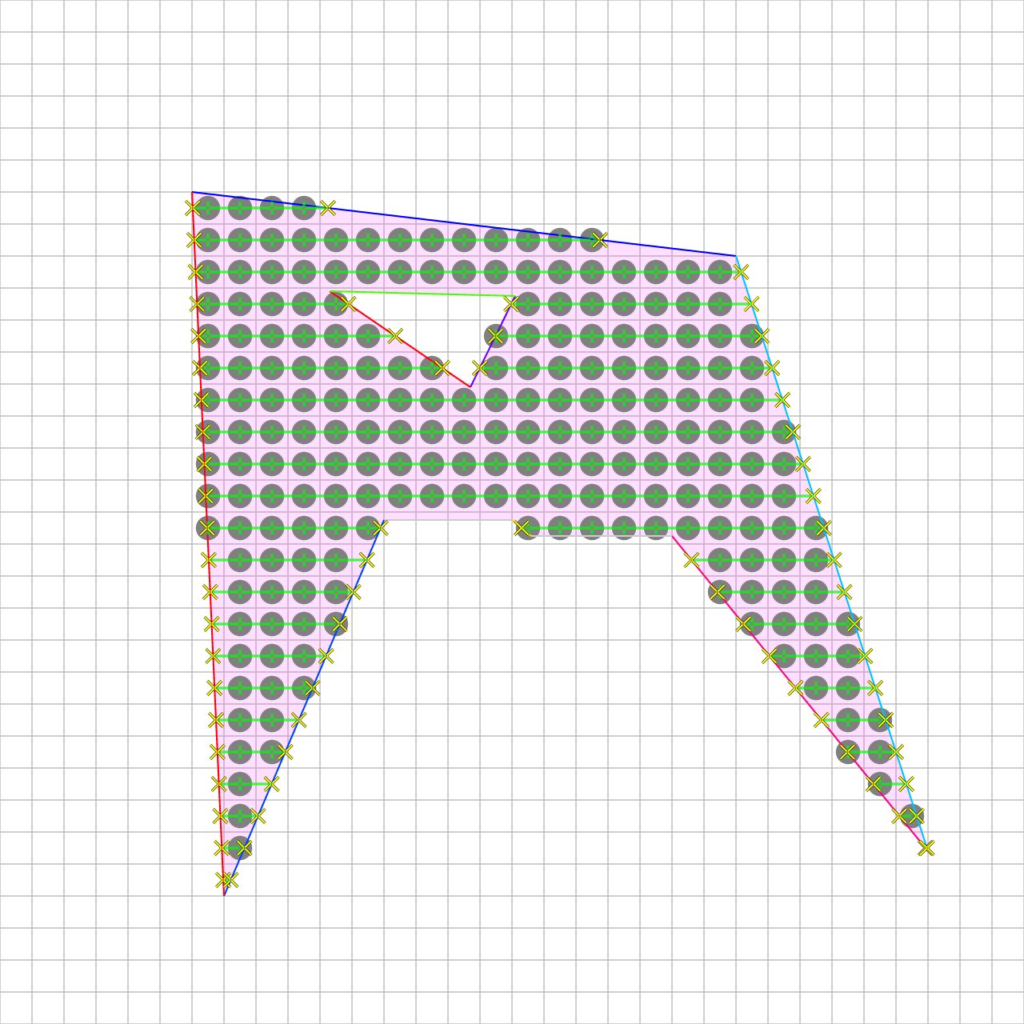
(Scanlines and centerpoints)

For each row (or “scanline”) we determine which edges encompass the something-point-5 part of the row. There will always be an even number. Then find the x-position of each of these. Then we fill in pairs, only those pixels within an x-pairs span.

Some simple optimizations include:

• presorting all the edges by lower-y value, so you just look at the next one to see if its in Y range

• using an x-step value for each active edge, as we step down each scanline, because we do render the scanlines sequentially

• discard horizontal edges, or any edge that doesn’t traverse a Y-point-five boundary

At first it did seem like a bother, but it all became easy to implement.

What about antialiasing? The output looks pretty blocky without it. You can always render bigger and scale down, perfectly respectable solution.

One easy thing I was tempted to try was, incorporate the x-position of each edge for partial coverage.
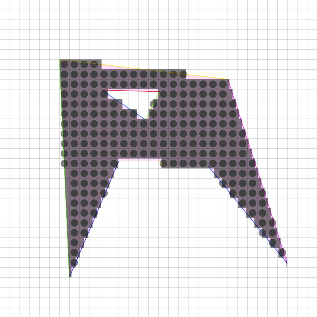
[A simplistic and flawed anti-aliasing approach]

Alas this would only help the side edges, and not the top edges, and just look funny

But… look closely at these illustrations. Go ahead, zoom in. They were all drawn using OmImageRgba8 and OmPolygon filling. And they’re antialiased very nicely! Next post will demonstrate a nice antialiasing technique that builds on this edge-sorting, and doesn’t involve downscaling.

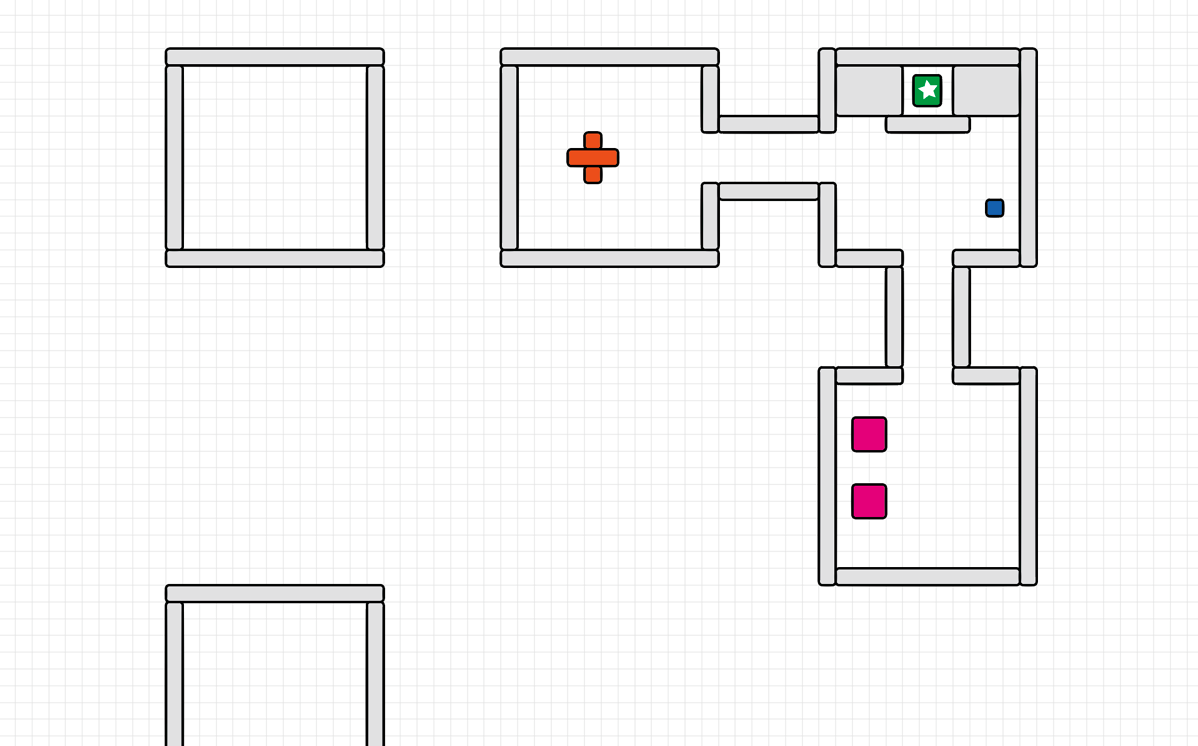
Collisions, Yet Again, Part 3.

This post is Part 3 of 3 about Metareal’s collision subsystem.

In Part 1 and Part 2, we described how boxes can fly through spaces, hit each other, push each other, and stop when they hit walls.

In this final Part we’ll look at a few glossed-over details… And then the rather glamorous feature which allows several boxes to be treated together as a composite volume.

The Fabric Of Space

I just read in the Wikipedia that empty space in our universe contains about a trillionth of an erg per cubic centimeter. That works out a millions of an erg per cubic meter. “Good heavens!”

But that’s not important. In the Meteral world, we need to know where things are. We consider each “thing” as a box-shape (or a collection of box shapes). This is described as a position (X,Y,Z), and a radius in each axis (Rx, Ry, Rz).

To detect collisions, both for physical movement and also for game triggers, we need to ask: “Which boxes, if any, are we touching?” One way would be to check every single box in the world.

CollisionPart3NoBins

Even for Metareal’s modest universe of about ten thousand anticipated objects, this would be quite slow. Time is framerate and all that.

There are a number of well-known techniques for optimizing this (K-dimensional trees & oct trees are two of them) but I chose a simple one: fixed-size bins. Since objects in Metareal are all in a bounded area about 1200 units across, and somewhat evenly distributed, this works well.

CollisionPart3Bins

Each bin is 16 units across. Why 16? Trial and error, and most objects are less than 16 units big. To check for a collision, we just look in the bin where our collider is (its center point), as well as the 26 bins adjacent to it. Ah, you say, But what about objects that are bigger than 16 units? Well… I put them in all the bins that they’d hit. It’s a little bit inelegant for large objects, but seems to work.

When an object moves, we see if its center has changed bins. If so, we remove it from all the bins it was in (usually just 1, but more for a big object) and add it to all the bins it will be in. Again, somewhat dorky for large objects, but it works for now.

Many bins are empty. To locate a bin, we index into a std::map<long, Bin> with a 48 bit hash derived from 16 bits each for X, Y, and Z bin-position. (With a 1200 unit world and 16 unit bins, could fit into 8 bits per axis and an int map index… but it’s fine.) The way std::map works, bins pop into existence the first time it is accessed.

Ball Vs Wall

In Part 2, we described how collisions know when to stop: When the thing moving or something it’s pushing hits a wall. This feature is actually very slightly deeper. Every object has an Inertia value, which represents how hard it is to push. And every movement has a Force value, which is how big an object it can push. If the Force is bigger than the Inertia, then the thing can be pushed. Else, it is stopped. In a chain of several objects moving, the original Force is transferred through all the pushed things.

CollisionPart3Chain

A wall is a thing with a relatively high Inertia. I’ve often had bugs where a Metareal room accidentally had a low Inertia, and would move around. It is disorienting and then the hallways no longer line up. 🙂

Complex Collision Volumes

I’ve found you can get quite far with a world whose only colliders are box-shaped. Especially in this game, where the physics are inherently… boxey! Still, it’s valuable to have other shapes, for certain kinds of puzzles where you push or manipulate pieces with corners or fitting areas and such.

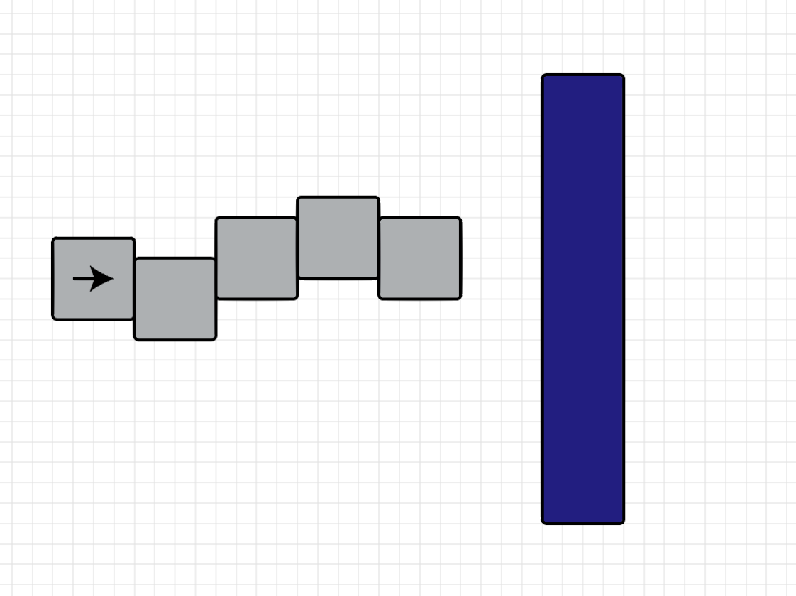
The implementation builds the technique described in Part 2, and is almost disappointingly simple. To move a compound collider, move each of its component boxes as a single box, and the resulting possible movement is whichever of them can move the least. When it pushes other objects, they each check how for their components can move.

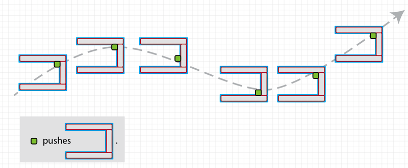
CollisionPart3Compound

Illustrated above is a simple volume pushing a compound volume.

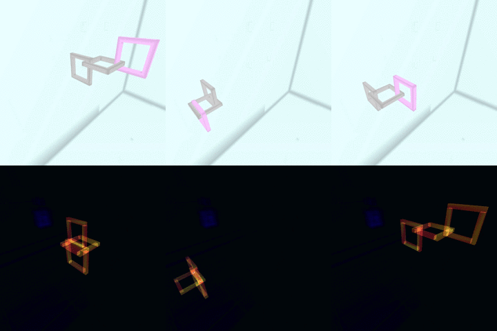
Shown below is the movement of several linked compound objects. It alternates between the game-render view, and a debug view showing the component volumes.

CollisionPart3linksLoop

Now, because I sometimes let my code evolve a bit too long before refactoring, the actual data structure is that each CollisionVolume object includes a std::vector of all its fused CollisionVolumes. And they all point to each other. Which is maybe an odd way to do it and slightly wasteful of space, but it works and that is that for now!

Engine: MeRenderWorld

And now, a few notes about the Metareal Engine architecture. As mentioned earlier, of course it’s silly to write my own, let’s move on.

The library presently consists of two major components: Rendering and Volume Management. The Rendering side deals with lists of triangles, groupings of parts, geometry lists, and shader graphs. The Volume Management side deals with detecting intersections of volumes, and notifying listeners. Physics is built on top of volume management, as a special case of responding to intersections.

In this post, I’ll talk about one aspect of Rendering.

MeRenderWorld

The class MeRenderWorld is presently the highest level container. An application may use several, certainly, but this is the top container on the library side.

An MeRenderWorld manages:

  • Lists of Parts (each part is a geometry list)
  • Cached geometry lists, grouping parts by material, so each material uses a single glDraw
  • References to materials (shader programs, for an OpenGL implementation)
  • Backing buffers for rendering post processing
  • List of render operations

The MeRenderWorld itself knows nothing about OpenGL; rather it deals with MeIMaterials and MeIPartRenderers and MeITextures and so on. For now there are only two implementations of each, one for OpenGL and one for FakeFL, which just records actions suitable for unit testing the library.

Often, one wants to describe a process by means of a document, perhaps in XML or similar. Describing the graph of draws and post-processing for a final scene frame is a perfect example of this. However, I have a strict policy of implementing code first, document second. Here I’ll show the code mechanism for building up a render graph.

The render graph is described as a strict, linear sequence of actions. It has to become one anyway (at least until glNext), so that’s the primitive. Here is an example setup:

    MeRenderWorld *rw = this->renderWorld;
    rw->addStepClear("", 0x123456);
    rw->addStepDraw(this->materialSky, "");
    rw->addStepDraw(this->materialOpaque, "");

Here we see that each frame will be created with three actions: a clear-to-color, and two material draws. Today this is, in fact, exactly two glDraw() calls, but that could change.

The empty strings are the names of frame buffers. The unnamed buffer, “”, is the default output buffer. This might be the screen or window, or be another buffer, depending later on the argument to rw->draw().

Here’s a more complex render sequence:

    rw->addStepClear("b0", this->bgColor);
    rw->addStepDraw(this->materialSky, "b0");
    rw->addStepDraw(this->material, "b0");
    addCopyingStep(rw, "b0", "b1");

    rw->addStepSetTextureColor("b1", this->materialTransparent, "texture1");
    rw->addStepDraw(this->materialTransparent, "b0");

    addCopyingStep(rw, "b0", "");

In this sequence, the background is cleared and then drawn with a skybox. Then, the opaque parts of the geometry are drawn onto a buffer named “b0”. This buffer is created on-demand by MeRenderWorld, you just have to name it, and it exists.

That first render is provided as a texture argument to the transparent material, in a uniform named “texture1”, which is then drawn onto “b0” also.

Lastly, “b0” is copied to the output. (addCopyingStep() is a macro which instantiates a screen-sized rectangle textured with one buffer, drawing to the other).

Here’s a frame of the output:

translucent

And there’s a peek into the Metareal Engine’s rendering component.